Unit 9 — Angles: Sun Position, Incidence Angle, Fresnel Reflection, Bifacial and Albedo
Big idea. A panel only collects the part of the beam that meets it face-on (the cosine law), and at steep angles more light bounces off the glass (Fresnel reflection). Bifacial modules also collect light reflected from the ground (albedo) through their rear side. This unit gives just enough geometry to understand light entering a module — no system siting or sizing.
Learning objectives
- Describe the Sun's position with zenith/altitude and azimuth; estimate noon zenith angle from latitude and season.
- Apply the cosine law to compute irradiance on a tilted surface.
- Compute Fresnel reflectance at normal incidence and describe how it grows with angle.
- Explain bifaciality, albedo and why they matter for module design.
Why this matters
Front-glass texture and anti-reflection coatings, cell texturing, the incidence-angle modifier on datasheets, and the boom in bifacial (glass–glass, TOPCon/HJT) modules are all angle-and-reflection engineering. In Lab 101-B you will measure the cosine law with a real cell.
Sun position in brief
The Sun's position is given by its zenith angle \(\theta_z\) (from straight up; altitude \(= 90° - \theta_z\)) and azimuth (compass direction). Because Earth's axis is tilted 23.44°, the declination \(\delta\) (the latitude where the Sun is overhead at noon) swings between +23.44° (June solstice) and −23.44° (December solstice). At solar noon:
where \(\phi\) is your latitude. In words: the noon Sun is as far from overhead as your latitude is from the declination.
Worked example 1 — noon Sun in Chicago (41.9° N)
June 21: \(\theta_z = 41.9 - 23.4 = 18.5°\) (altitude 71.5°). Equinox: 41.9°. December 21: \(41.9 + 23.4 = 65.3°\) (altitude 24.7°).
The cosine law
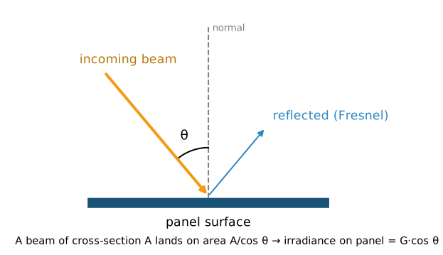
A beam of cross-section \(A\) striking a surface at angle \(\theta\) from the surface's normal (the line perpendicular to it) spreads over an area \(A/\cos\theta\). The irradiance on the surface is therefore
Worked example 2 — tilted panel at noon
A south-facing panel in Chicago tilted 30° from horizontal. At the equinox noon the Sun is 41.9° from vertical, so the angle between beam and panel normal is \(41.9 - 30 = 11.9°\). With DNI = 900 W/m², the beam irradiance on the panel is \(900 \cos 11.9° = 881\) W/m². In December (65.3°): angle 35.3°, \(900 \cos 35.3° = 734\) W/m² (if DNI were still 900; in reality it is lower at higher air mass).
Fresnel reflection
Whenever light crosses from one refractive index to another, part reflects. At normal incidence:
- Air → glass (\(n = 1.5\)): \(R = (0.5/2.5)^2 = 4.0\) %.
- Air → bare silicon (\(n \approx 3.9\) at 600 nm): \(R = (2.9/4.9)^2 \approx 35\) %.
At oblique angles the full Fresnel equations treat the two polarisations separately; for unpolarised light the reflectance stays near its normal value up to about 40–50°, then rises steeply toward 100 % at grazing incidence. (For glass, the reflected light is fully polarised at Brewster's angle, \(\arctan 1.5 = 56.3°\).)
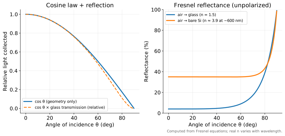
| Angle θ | cos θ | R air→glass | R air→Si (n = 3.9) |
|---|---|---|---|
| 0° | 1.000 | 4.0 % | 35.0 % |
| 30° | 0.866 | 4.2 % | 35.0 % |
| 45° | 0.707 | 5.0 % | 35.0 % |
| 60° | 0.500 | 8.9 % | 35.0 % |
| 70° | 0.342 | 17.1 % | 36.0 % |
| 80° | 0.174 | 38.8 % | 43.1 % |
(Computed here. Real modules include AR-coated glass, encapsulant and textured cells, so the full optical stack performs better than bare surfaces.)
Datasheets and energy models capture this with an incidence angle modifier (IAM) — the ratio of light coupled into the cells at angle θ to that at normal incidence, beyond the cosine factor.
Why cells are textured and coated
A 35 % reflection loss from bare silicon would be ruinous. Cells use (1) pyramid texture, so reflected light hits a neighbouring pyramid and gets a second chance (SOL 102 Unit 8), and (2) a silicon-nitride anti-reflection coating (SOL 102 Unit 9). Together with encapsulation, reflection drops to a few per cent. Module glass often carries a porous-silica AR coating that reduces the 4 % front-glass reflection (gain of order 2–3 % in transmission; estimate).
Bifacial modules and albedo
A bifacial module has a transparent back (glass or clear backsheet) and cells that collect light on both faces. The rear receives light reflected from the ground and scattered from the sky. Albedo is the fraction of light the ground reflects (rough values: grass ≈ 0.2, dry concrete ≈ 0.3, white roofing ≈ 0.6–0.8, fresh snow ≈ 0.8–0.9; estimates — measured values vary).
Bifaciality is the ratio of rear-side to front-side efficiency at STC. Typical values (ITRPV-type ranges; estimate): PERC ≈ 70 %, TOPCon ≈ 80 %, HJT ≈ 85–90 %. Rear-side gain in the field is typically 5–15 % of front energy depending on albedo, height and row spacing (estimate).
Worked example 3 — rough bifacial gain
Front irradiance 900 W/m². Rear irradiance ≈ 10 % of front for grass at typical mounting height (assumed) = 90 W/m². Bifaciality 0.80 → effective extra = \(0.80 \times 90 = 72\) W/m², i.e. an 8 % boost. On snow (rear maybe 25 % of front, assumed) the boost could reach ~20 %.
Common misconceptions
Misconceptions
- "Tilting a panel 10° off the Sun loses 10 %." Cosine loss at 10° is only 1.5 % (\(\cos 10° = 0.985\)). Losses grow fast only beyond about 40–50°.
- "Glass reflects 4 % so the module loses 4 %." Encapsulant, cell coatings and texture add other interfaces; AR-coated glass reduces the front loss.
- "Bifacial modules double the output." The rear sees far less light than the front; typical gains are single-digit to low-double-digit per cent.
What this means for manufacturing and the job
- Glass AR coating, cell texture and SiNₓ thickness are process parameters monitored daily (reflectance measurements; SOL 302/401).
- Bifacial cell design (rear passivation, rear metal grid, glass–glass laminates) is mainstream in TOPCon and HJT production (SOL 303/304).
- IAM and bifaciality are measured in module qualification (SOL 401/403).
Key equations
| Equation | In words |
|---|---|
| \(\theta_{z,\text{noon}} = \lvert\phi-\delta\rvert\) | noon zenith from latitude and declination |
| \(G_\text{surface} = G_\text{beam}\cos\theta\) | cosine law |
| \(R = \left(\frac{n_1-n_2}{n_1+n_2}\right)^2\) | normal-incidence reflectance |
Review questions
1. What fraction of a beam is intercepted at 60° incidence (ignoring reflection)?
cos 60° = 0.50.
2. Normal-incidence reflectance from glass (n = 1.5) into EVA (n = 1.48)?
((1.5−1.48)/(2.98))² ≈ 4.5 × 10⁻⁵ — essentially zero, which is why index-matched encapsulant hides internal interfaces.
3. Noon zenith angle in Austin, TX (30.3° N) on the June solstice?
30.3 − 23.4 = 6.9°.
4. Why does reflection matter more in the morning and evening?
Large incidence angles: both cosine loss and Fresnel reflectance increase (glass R rises from 4 % to ~9 % at 60° and ~17 % at 70°).
5. Rear irradiance 120 W/m², bifaciality 0.85: effective extra front-equivalent irradiance?
0.85 × 120 = 102 W/m².
Sources
- PVEducation, "Solar Radiation on a Tilted Surface", "Declination Angle", "Anti-Reflection Coatings" pages.
- Hecht, Optics — Fresnel equations.
- ITRPV 17th ed. (2026) — bifacial technologies (bifaciality figures quoted as typical ranges; verify against the current edition).
- Albedo values: general literature ranges, marked as estimates.